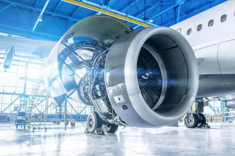
Reverse engineering combined with 3D scanning and printing offers a powerful and innovative approach to product development and manufacturing. This article explores the process of incorporating 3D scanning and 3D printing techniques in reverse engineering and highlights the benefits of this combination.
Introduction
Defining Reverse Engineering and Its Relevance to 3D Printing
Reverse engineering is the process of analyzing an existing object or product to uncover its design, construction, and function. It involves taking apart a finished product and studying it in detail to understand how it was made, what materials were used, and how it works. This information can then be used to create a replica or improve upon the original design.
In recent years, reverse engineering has become increasingly important in the manufacturing industry because of the rise of 3D printing technology. With 3D printing, engineers are able to take data from scanned objects or parts and turn them into digital models that can be manipulated for production purposes. Reverse engineering combined with 3D printing allows manufacturers to create exact replicas of existing products or make modifications based on customer feedback.
Moreover, reverse engineering using scanning technologies such as laser scanners can provide precise measurements that allow for accurate reproductions or adaptations without damaging the original part. In addition, this approach enables more efficient maintenance processes by replacing broken components quickly instead of having long downtime due waiting for replacement parts.
Overall, reverse engineering with 3D printing offers numerous benefits including reduced costs associated with manufacturing new products from scratch while maintaining high quality standards through replicating proven designs accurately. As we move forward towards Industry 4.0 era where customization becomes crucially important as well as sustainability aspect; adopting this methodology will play an even greater role in creating highly customized solutions at affordable cost while keeping environmental impact minimum through reusing already available resources efficiently rather than discarding them altogether which cause negative consequences on environment such as pollution etcetera.
Step 1: 3D Scanning and Mesh Conversion
Understanding 3D Scanning
Reverse engineering with 3D printing involves the process of creating a digital replica of an existing physical object. This is where 3D scanning comes in handy. 3D scanning is the process of using a device that captures the shape, size and texture of an object to create a digital model. It can be done using various types of devices such as structured light scanners, laser scanners or photogrammetry.
Structured light scanners work by projecting patterns onto the surface of an object and then capturing images that are used to reconstruct its geometry. Laser scanners use lasers to measure distances between points on an object’s surface while photogrammetry uses multiple photographs taken from different angles to generate a point cloud which is then converted into a mesh model.
The choice of scanner largely depends on the type and complexity of the object being scanned as well as other factors such as cost, speed, accuracy and resolution required for your project.
Converting Mesh Model for 3D Printing
Once you have captured data from your scan, it needs to be processed before it can be printed in three dimensions. The raw data generated by most scanning processes typically results in what is known as a point cloud – thousands or millions of individual points representing specific locations on an object’s surface.
To turn this point cloud into something usable for printing requires converting it into some kind of polygonal mesh-based format such as STL (STereoLithography) which contains all necessary information about surfaces’ geometries required for successful printout creation.
Mesh models are constructed by connecting these points together with lines or triangles based on their proximity and orientation relative to one another until they form complete shapes suitable for CAD modeling purposes like adding fillets etcetera so we could improve manufacturing capabilities alongside keeping geometrical features intact during production stages without sacrificing structural functionalities due lack thereof per se .
Some software tools let engineers manipulate meshes more directly than others; however, they typically allow you to perform operations such as smoothing, simplification or modification of the mesh before exporting it to STL format. These modifications are necessary because not all point clouds will be perfect and require some cleaning up.
Step 2: Mesh to Solid CAD Conversion
Understanding Mesh to Solid Conversion
Once the 3D scan has been converted into a mesh model, it is essential to convert it into a solid CAD model for further editing and optimization. Mesh models are made up of thousands or even millions of tiny triangular faces that make them difficult to edit and manipulate. Therefore, converting them into a solid CAD model makes the design process much easier.
The conversion process involves taking the mesh data and reconstructing it as a watertight surface or solid body using specialized software such as Geomagic Design X or Autodesk ReCap. This transformation allows you to easily modify features like holes, fillets, chamfers, and other geometric shapes. It also enables you to apply engineering principles such as stress analysis and simulation.
Editing the Solid CAD Model
Although converting from mesh data to solid CAD is an important step in reverse engineering with 3D printing technology, this alone does not guarantee a perfect final result. The resulting surface generated during conversion may contain inconsistencies that need correction before proceeding with additional modifications.
Fortunately, modern 3D modeling software provides powerful tools for inspecting and correcting errors in your newly created solid model. These include automatic error detection functions that can detect anomalies such as self-intersections or gaps in surfaces caused by missing triangles on scanned objects.
After identifying these discrepancies through inspection tools like edge analysis or curvature deviation checks, you can then use various techniques like surfacing algorithms (such as NURBS) or manual manipulation of vertices/edges/faces until all issues have been fixed.
Step 3: CAD Model Modification and Testing
Modifying the CAD Model
After the 3D scan is complete, you will have a detailed point cloud data of the object you want to reverse engineer. This point cloud data can be imported into various software tools such as Geomagic Design X or SolidWorks where it can be converted into a CAD model using surface reconstruction algorithms. However, this CAD model may not always be perfect and often requires modification to achieve accuracy.
CAD model modification involves adjusting parts of the model that do not match with the original object’s dimensions. This process is done by comparing different parts of the scanned object with their corresponding dimensions in the CAD design, identifying mismatches and making adjustments accordingly. Some common editing techniques include trimming surfaces, adding fillets or chamfers, blending surfaces together and removing holes.
It is important to note that while modifying your CAD model, you should maintain consistency between all sections so that they fit seamlessly together when printed in 3D.
Testing the CAD Model
Once modifications are made on your computer-aided design (CAD) file using specialized software applications like CATIA V5 and AutoDesk Inventor Fusion among others; it’s time for testing! The goal here is ensuring that your newly created virtual component works perfectly before moving onto production runs.
Testing involves running simulations on modified models to ensure functionality. Finite Element Analysis (FEA), Computational Fluid Dynamics (CFD) analysis or kinematic simulation are some common testing methods used in engineering models.
FEA helps test stress levels within components while CFD analyses fluid flow through designs which help identify potential blockages in piping systems. Kinematic simulation tests how mechanical components work under different conditions providing insight into any necessary redesigns needed for optimal performance output.
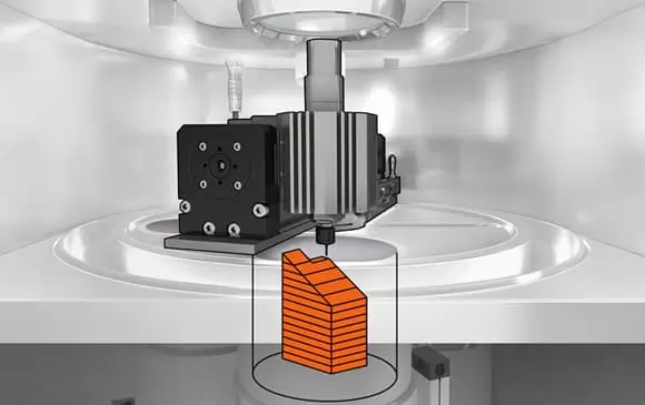
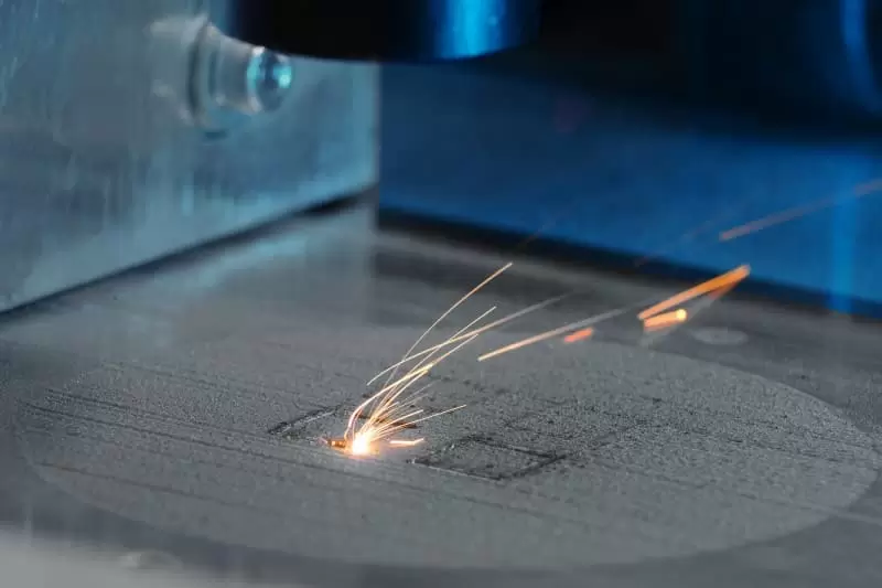
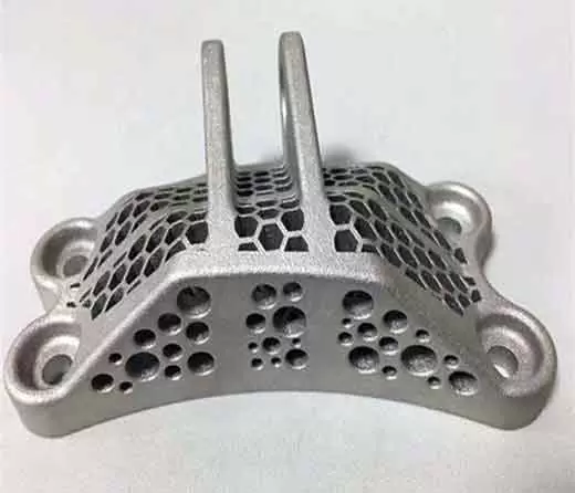
Step 4: 3D Printing the Final Part or Prototype
The Process of 3D Printing the Final Part or Prototype
Once the reverse engineering process is complete and a 3D model has been created, it’s time to move on to printing the final part or prototype. This step involves preparing the 3D model for printing and selecting the appropriate printer settings.
The first step in preparing for printing is to ensure that all necessary support structures are included in the design. Support structures help to hold up overhanging parts during printing, preventing them from collapsing under their own weight. Once this is done, it’s important to optimize printer settings such as layer height, infill density, and print speed based on factors like material type, intended use of the printed object, and desired level of detail.
Before beginning the actual printing process, it’s essential to check that everything is set up correctly by running a test print using a small section of your design. This helps identify any potential issues with printer calibration or other problems that may arise during full-scale production.
When everything has been checked and double-checked, it’s finally time to start printing! Depending on size and complexity of your design this can take anywhere from minutes up through hours or even days.
Finally when finished we must carefully remove supports if applicable then polish out any rough areas using sandpaper before finishing off with paint coatings as required depending upon end-use application which leads us onto our next topic – materials selection!
Conclusion
Benefits and Challenges of Using Reverse Engineering with 3D Printing
In conclusion, reverse engineering with 3D printing has numerous benefits in the manufacturing industry. One major advantage is that it allows for faster and more cost-effective production of replacement parts or prototypes. This technology enables manufacturers to capture physical data from existing objects, create a digital model from that data, and then produce an exact replica using a 3D printer. Furthermore, reverse engineering can also be used to improve the design of existing products by analyzing their strengths and weaknesses.
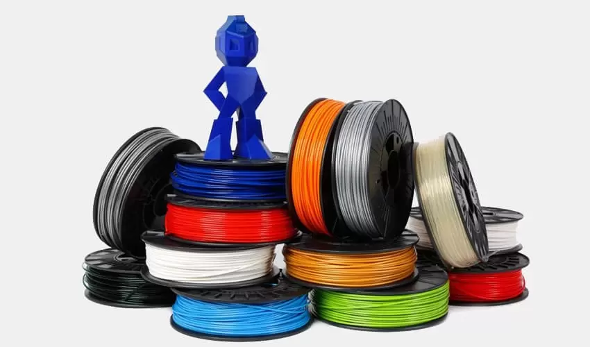
However, there are also some challenges associated with reverse engineering using 3D printing technology. The process requires specialized software tools and equipment which can be costly for small-scale operations. Additionally, not all materials can be easily scanned or printed using this technique leading to limitations in its application.
Despite these challenges, the potential benefits of reverse engineering combined with 3D printing make it an exciting area for further exploration in the manufacturing industry. As this technology continues to evolve and become more accessible, we will likely see even greater advancements in product development and customization capabilities.
How to use 3D scanning and 3D printing for reverse engineering?
3D scanning serves as the initial step in the reverse engineering process. A 3D scanner captures the geometry and surface details of an existing object, converting it into a digital 3D model. This scanned model can then be manipulated and modified using computer-aided design (CAD) software. Subsequently, 3D printing comes into play by utilizing the digital model to recreate a physical prototype. Multiple iterations can be produced, allowing for testing, refining, and optimizing before actual manufacturing takes place. The combination of 3D scanning and 3D printing empowers engineers to replicate, analyze, and enhance existing products or components.
What are the benefits of reverse engineering in 3D printing?
Reverse engineering in combination with 3D printing offers several significant benefits. First, it allows for the creation of accurate replicas of complex or hard-to-source components without access to original design files. This is particularly useful for obsolete parts or for recreating delicate historical artifacts. Second, reverse engineering in 3D printing enables design improvements and modifications through the freedom to iterate and test different versions rapidly. Engineers can evaluate and optimize functionality, performance, and manufacturability before finalizing the design for production. Additionally, reverse engineering with 3D printing significantly reduces development time and cost by eliminating the need for traditional tooling and manufacturing processes.
Can a 3D scanner help with reverse engineering?
Absolutely, a 3D scanner is a crucial tool for reverse engineering. It captures the existing object’s intricate details, dimensions, and shape, converting it into a high-resolution digital model. The scanned model provides engineers with a starting point for reverse engineering, allowing them to analyze and modify the design as needed. 3D scanners can capture both external and internal features, providing comprehensive data for reverse engineering processes. By enabling the creation of accurate digital representations, 3D scanners facilitate the precise reproduction of objects and aid in subsequent modifications or enhancements during the reverse engineering process.