Table of Contents:
- Introduction
- Technical Drawing Fundamentals
- Geometric Constructions
- Sectional Views
- Auxiliary Views and Detail Drawings
- Standards and Conventions
- Computer-Aided Drafting (CAD)
- Conclusion
–
1. Introduction
Engineers and manufacturers continue to use drawings to communicate how to create things. Engineering drawings are a form of communication that describes the shapes, sizes, and features of objects. In this article, we will discuss the importance of engineering drawing, its history, and the different types of engineering drawing.
Definition and Importance of Engineering Drawing:
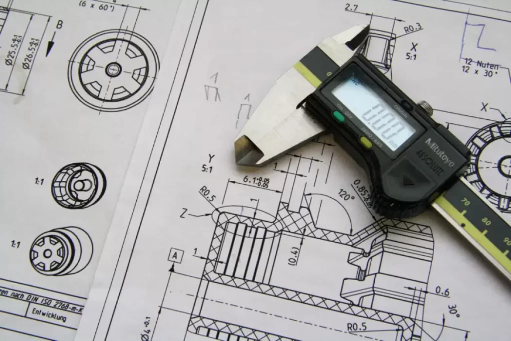
Engineering drawing, also called technical drawing, is the language used by engineers and manufacturers to describe products and their manufacturing processes. It is a graphical representation of an object or system, created using computer-aided design (CAD) software, or by hand using drafting tools such as pencils, rulers, and compasses.
An engineering drawing provides technical information necessary to manufacture and assemble a product. It is used for product development, production planning, and quality control. These drawings include detailed information about dimensions, geometric features, and manufacturing tolerances, all of which are critical for the product’s design and function.
Types of Engineering Drawing:
There are several types of engineering drawing, each of which serves a specific purpose. The three main types of engineering drawings are:
- Product Drawings: These drawings provide information about the shape, size, and features of a product. Examples include assembly drawings, part drawings, and detail drawings.
- Process Drawings: These drawings provide information about the manufacturing process of a product. Examples include welding drawings, machining drawings, and casting drawings.
- Installation Drawings: These drawings provide information for the installation of a product. Examples include electrical wiring diagrams, piping diagrams, and foundation plans.
–
2. Technical Drawing Fundamentals
To create accurate and comprehensive engineering drawings, it is essential to have a strong foundation in technical drawing fundamentals. In this section, we will explore the basic concepts and techniques used in technical drawing.
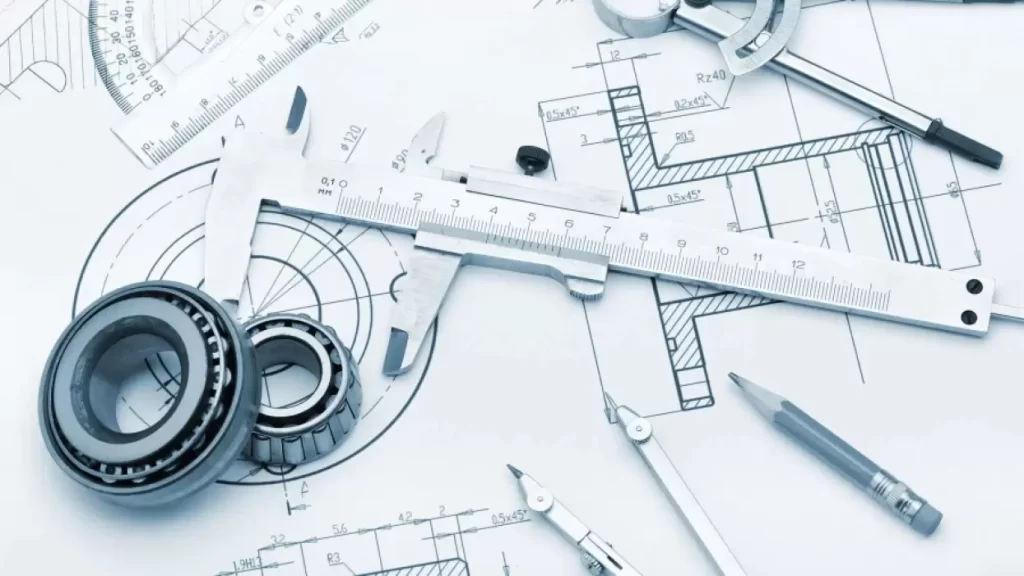
Drawing Tools and Materials:The tools and materials used in technical drawing have evolved over time, and today, there are many digital tools available in addition to traditional drafting tools. The most commonly used traditional tools include pencils, rulers, T-squares, compasses, erasers, and protractors.
Types of Lines and Hatching:In technical drawing, different types of lines are used to convey information. Lines are used to represent the edges of objects, hidden lines, construction lines, centerlines, and dimension lines. Hatching is also used to provide a visual representation of materials and surfaces.
Scale Drawings and Dimensioning:Scale drawings allow for the representation of large objects on a smaller-sized drawing sheet. Dimensioning is the process of adding numerical values to scaled drawings to specify the size of objects and their relationship to each other.
Orthographic Projections:Orthographic projection is used to create two-dimensional drawings of three-dimensional objects. It involves projecting the object onto three perpendicular planes (front, top, and right), and the resulting views are called the front view, top view, and right-side view.
–
3.Geometric Constructions
In technical drawing, there are several fundamental geometric shapes that are used as building blocks for more complex shapes. In this section, we will explore basic geometric shapes and their constructions.
Basic Geometric Shapes and Their Constructions:The basic geometric shapes used in technical drawing include the square, rectangle, circle, ellipse, polygon, and irregular shape. Constructions of these shapes involve the use of various drawing techniques such as straight-edge and compass.
Circles, Arcs, and Ellipses:Circles, arcs, and ellipses are commonly found in technical drawing. The construction of these shapes involves the use of a compass and is essential for creating more complex shapes such as cylinders and cones.
Polygons and Irregular Shapes:Polygons are shapes made up of straight lines that meet at corners. They are commonly used for creating shapes such as squares, triangles, and hexagons. Irregular shapes are shapes that do not have a mathematical formula to describe them.
Isometric Drawing:Isometric drawing is a technique used to create three-dimensional drawings of objects. It involves drawing the object at an angle that clearly shows all three dimensions (length, width, and height).
–
4.Sectional Views
Sectional views are used in technical drawing to show the internal features of an object. In this section, we will explore the different types of sectional views, cutting planes, and section lines.
Types of Sectional Views:The three most common types of sectional views are the full section, half section, and offset section.
Cutting Planes and Section Lines:Cutting planes are imaginary planes that are used to represent where an object is being cut. Section lines are used to indicate where the object has been cut and allow for the internal features to be seen clearly.
Partial and Revolved Sections:Partial sections are used when only a portion of an object needs to be shown in detail. Revolved sections are used to show the internal features of objects that are symmetric around a central axis.
Conventional Representations:Conventional representations are used in technical drawing to communicate information about materials, surface finishes, and other important features. These include hatch patterns, symbols, and abbreviations.
–
5. Auxiliary Views and Detail Drawings
Auxiliary views and detail drawings are used in technical drawing to show additional information about the object being drawn. In this section, we will explore the purpose and use of auxiliary views and detail drawings.
Purpose and Use of Auxiliary Views:Auxiliary views are used to show features of an object that cannot be seen clearly in the primary views. They are typically drawn at an angle and provide additional information about the object’s shape and size.
Detail Drawings and Enlarged Views:Detail drawings are used to show a specific part of an object in detail. Enlarged views are used when the detailed view is too small to show all the required information.
Assembly Drawings and Exploded Views:Assembly drawings are used to show how parts of an object fit together. Exploded views are used to show the individual parts of an object and how they fit together.
–
6. Standards and Conventions
To ensure that technical drawings are accurate and consistent, there are standards and conventions that must be followed. In this section, we will explore these standards and conventions.
ASME Y14 Standards:The American Society of Mechanical Engineers (ASME) has developed a set of standards for technical drawing, including the Y14 series of standards. These standards provide guidelines for dimensioning, tolerancing, and other important aspects of technical drawing.
ISO Standards:The International Organization for Standardization (ISO) has also developed a set of standards for technical drawing. These standards are similar to the ASME Y14 standards but are used primarily outside of the United States.
Title Blocks and Borders:Title blocks and borders are used to provide important information about the drawing, including the name of the object being drawn, the person who created the drawing, and the date it was created.
Tolerancing and Surface Finish Symbols:To communicate information about manufacturing tolerances and surface finishes, symbols are used in technical drawing. These symbols indicate the acceptable range of variation for dimensions and surface finishes.
–
7. Computer-Aided Drafting (CAD)
Computer-aided drafting (CAD) has revolutionized technical drawing, allowing for faster and more accurate creation of technical drawings. In this section, we will explore the advantages and disadvantages of CAD, common CAD software, and its application in engineering drawing.
Advantages and Disadvantages of CAD:CAD software provides several advantages over traditional drafting methods, including faster creation of drawings, easier editing, and the ability to share drawings electronically. However, there are some disadvantages, including the cost of the software, the need for specialized training, and the risk of computer crashes, and data loss.
Common CAD Software:There are several CAD software options available on the market, including AutoCAD, SolidWorks, and CATIA. Each software has its own strengths and weaknesses, and the choice of software will depend on factors such as cost, ease of use, and required features.
Application in Engineering Drawing:CAD software is widely used in engineering drawing for its ability to create accurate 3D models, perform simulations, and generate bill of materials (BOM) lists. It is used in several industries, including automotive, aerospace, and construction.
–
8. Conclusion
Engineering drawing is a critical skill for engineers and manufacturers, providing a way to communicate the technical information necessary for product development, production planning, and quality control. In this article, we explored the importance of engineering drawing, its history, and the different types of engineering drawing. We also discussed technical drawing fundamentals such as drawing tools and materials, geometric constructions, and sectional views. Finally, we explored the standards and conventions of technical drawing, the use of CAD software, and its application in engineering drawing. The development of these skills will ensure that engineers can continue to create accurate and comprehensive engineering drawings that support the design and production of high-quality products.